Arduino Quadcopter - V3
Testing
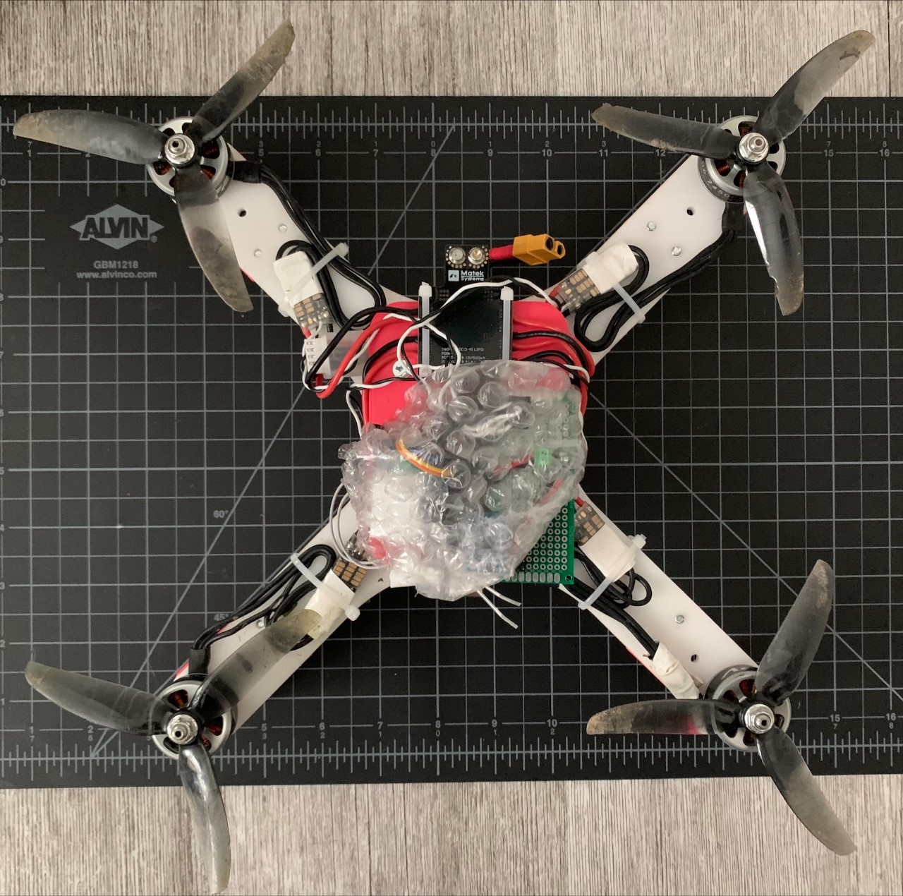
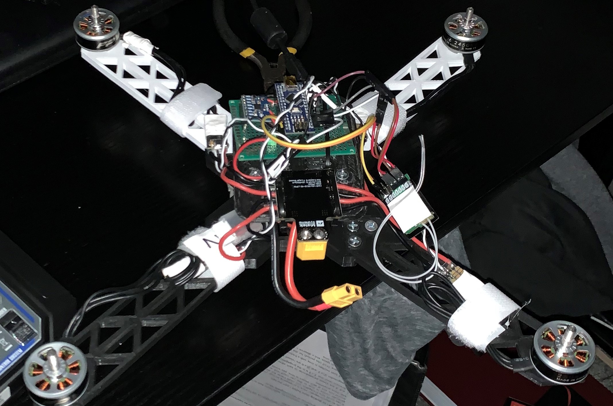
This Drone required re-tuning of the PID Controller due to the new moments of inertia of the assembly. In the summer of 2022 I was able to take flight again in the improved design. The laser cut frame has much more strength than the 3D printed plastic, and it can much better resist uneven moments during landing.
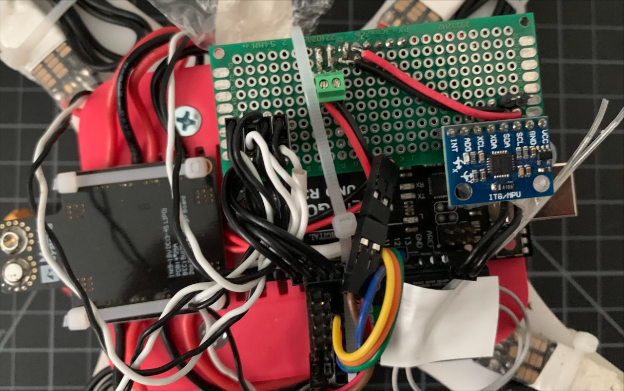
With a small budget, this entire electronics system costed less than $50, not including the motors. See the orientation of the MPU-6050 Accelerometer and Gyroscope. I also protoyped a board to power the Arduino and radio receiver from the battery. This hat (green) assisted to connect all components of the system.

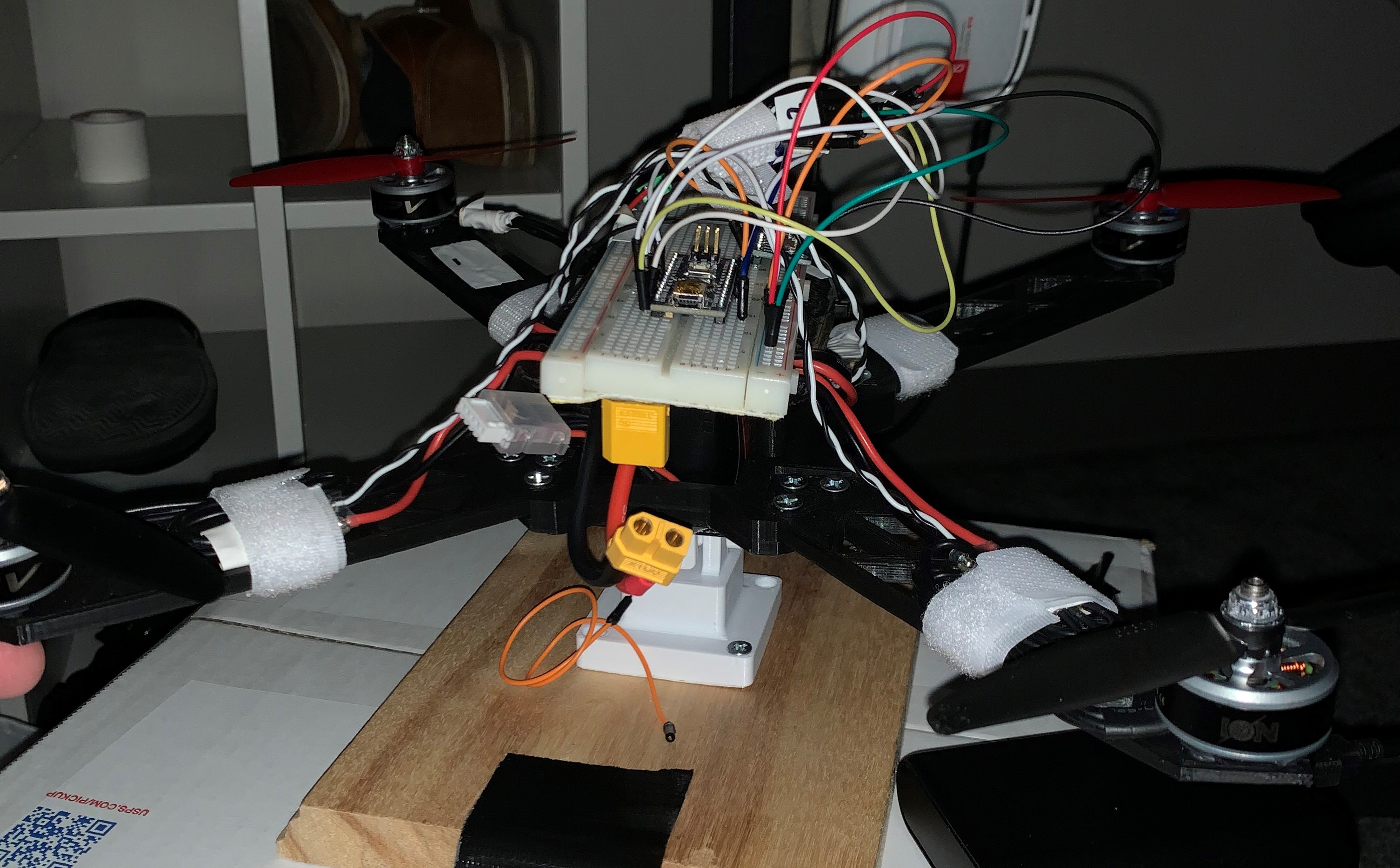
You can see some 3D print imperfections in the landing feet.
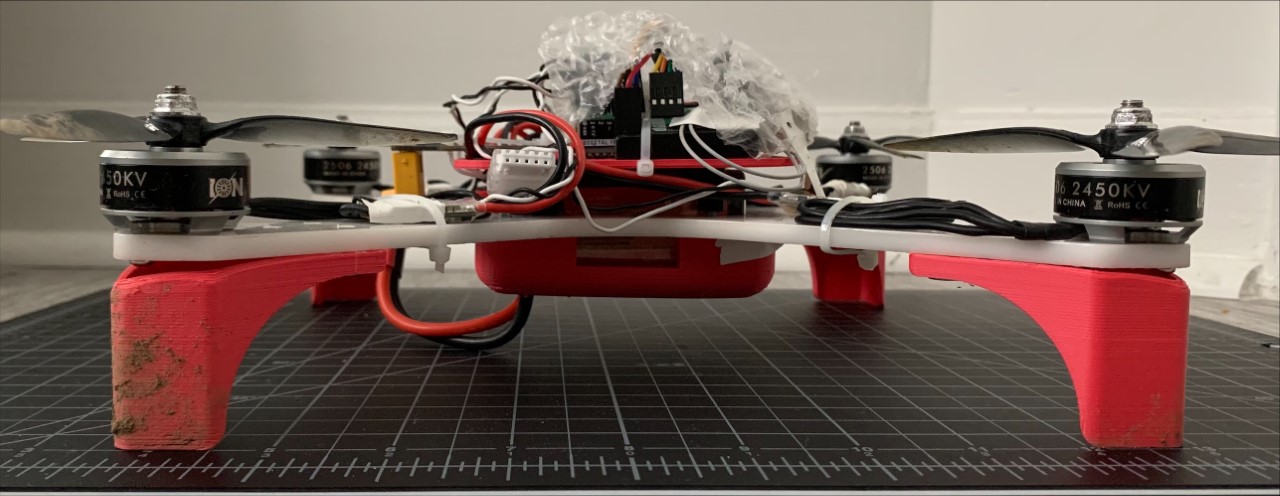
I love the bubblewrap to make an attempt at protecting the sensitive electronics.
Design
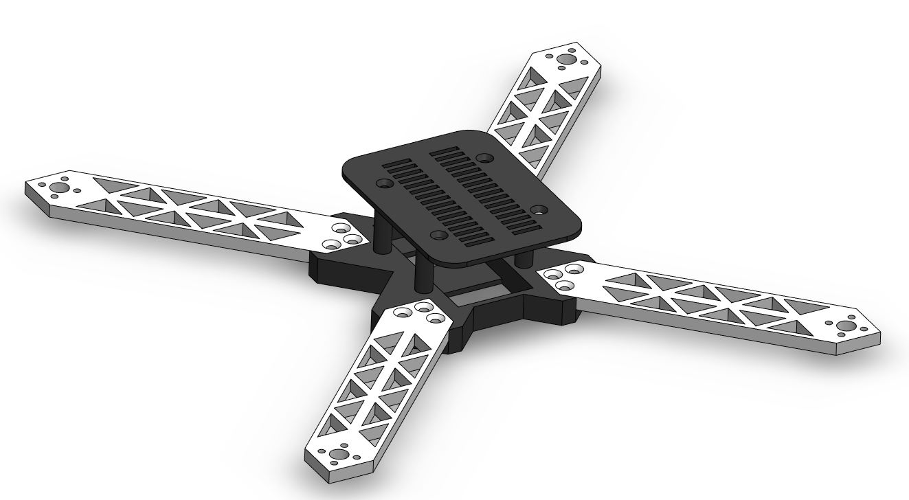
I optimized the Verision Below to use laser cut acrylic plastic and have 3D printed landing feet and battery bay. The top electronics stack was reprinted and reused from V2. A potential improvement on the electronics stack is to miniaturize it with a circuit board design program. Also, an electronics enclosure could be useful.
Version 2
Assembly and Testing
Electronics assembly of Version 2 was definitely a long process and learning experience. From crimping to soldering, I needed to relearn a lot of lost electronics skills. I also began programming and testing a PID Controller by mounting the prototyped drone on a one axis tilt, such that roll and pitch could be tested independently (See funny breadboard drone). After determining I needed more PWM pins and processing power for the drone's controller, I swapped to an Arduino Uno instead of an Arduino Nano. I brought this model into the field to tune the PID Controller, and after a few broken arms, the drone slowly lifted off of the ground.
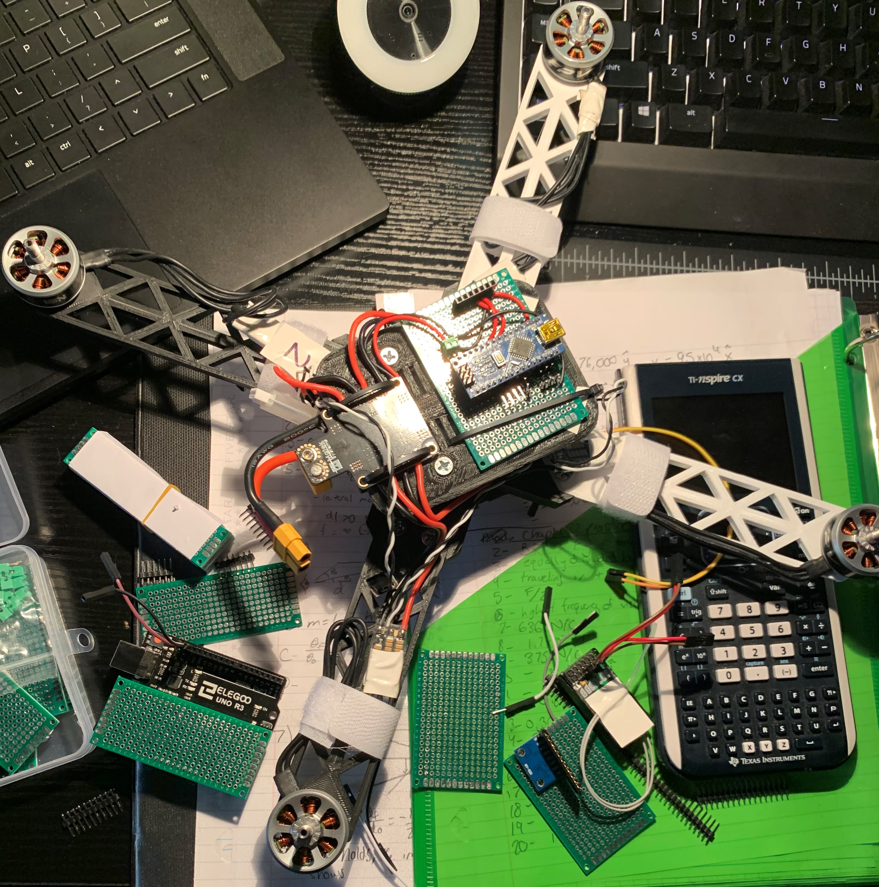
The model above would later be tuned, modified, and flown.
Design
I had hoped that this version would be the first to take flight, so I spent extra time in the design phase to ensure my 3D prints would not be a weakness, like they were for the first version. I implemented a design with a battery bay, and separate arms connecting to the central hub. The battery is then covered with another hood, where the electronics would be mounted. I then went on to manufacture this design.
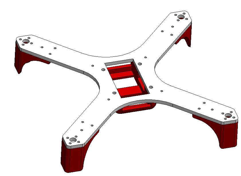
Version 1
Design
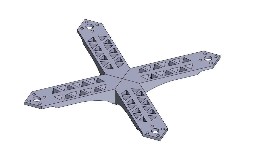
Version 1 was a test run for designing the quadcopter frame and the motor attachments. This model was then 3D printed and tested by mounting the motors. I learned that I would need a centralized hub for the electronics, battery, and controller. This would be implemented in V2.
I used an isogrid pattern on the arms to decrease weight and 3D printing cost. This idea was also used to a greater extent on the V2 arms.